The Technology

The Technology

For the love of Technology and People who love Aircraft, Spacecrafts, Scientific Tools, and Facilities capable of performing incredible tasks.

Post Top Ad

LightBlog

Post Top Ad

Your Ad Spot

January 29, 2021

Dawn: To Asteroids with Ion Propulsion

January 29, 2021 0

Dawn Mission was a remarkable journey to the earliest objects discovered in the asteroid belt: Giant Asteroid Vesta and Dwarf planet Ceres.

Mission Objectives

NASA’s main goal was to understand the origin and evolution of our solar system. Visiting Ceres and Vesta was crucial for this as these protoplanets were some of the earliest objects to form alongside other planets. The three major scientific objectives for the mission were:

  1. Capture the earliest moments in the origin of solar systems and realize the conditions under which these objects formed.

  2. Determine the nature of building blocks of planets to improve our understanding of the formation of terrestrial planets.

  3. To gauge the difference between Ceres and Vesta which followed different evolutionary paths to understand what parameters control that evolution.


Mission Timeline

Launch 

27th September 2007

Mars Gravity Assist

17th February 2009

Arrival at Vesta

16th July 2011

Departure from Vesta 

5th September 2012

Arrival at Ceres

5th March 2015 

End of prime mission

June 2016 

Start of 1st extended mission 

July 2016 

Start of 2nd extended mission 

October 2017 

End of Mission 

1st November 2018

Dawn Spacecraft 

Solar Arrays: Solar arrays are 8.3 meters long and 2.3 meters wide each. On these arrays are 11480 individual photovoltaic cells which can convert 28% of solar energy it receives into electrical energy. These arrays had a gimbaled connection which allowed them to rotate any desired angle to face the Sun.  


Antennas: Dawn had 2 types of antennas onboard, for communication with the earth through NASA’s Deep Space Network. And only one of those could be used at a time. It had 1 Large 1.52-meter diameter parabolic High-Gain antenna and three low gain antennas for when the spacecraft was not pointing high-gain antenna towards Earth.


Science Payload 

  1. Framing Camera: FC mapped Vesta and Ceres through the clear filter and 7 bandpass filters allowing the wavelengths from visible to near-infrared. The camera was used for understanding surface geomorphology and physical parameters of the asteroids as well as for orbit navigation. 

  2. Visible and Infrared spectrometer: VIR spectrometer consisted of 3 modules Optical system, proximity electronics, and cryocooler. It could see from 0.3 to 5 microns covering near-ultraviolet, visible and infrared regions of the spectrum.  

  3. Gamma Ray and Neutron Detector: The instrument allowed spacecraft to measure the elemental composition of Ceres and Vesta. A total of 21 sensors with a wide field of view was used to detect energy from gamma rays and neutrons that were reflected or emitted by celestial bodies. It could reveal atomic constituents of the surface of Ceres and Vesta down to the depth of 1 meter.


Ion Propulsion

Dawn spacecraft has three 41-centimeter-diameter ion thrust units(8.9 kg each) which are movable in two axes to control spacecraft attitude. Two of these thrusters were necessary to complete the mission but a third one was carried as a spare. These thrusters work by using an electrical charge to accelerate ions from xenon fuel up to a maximum rate of 3.25 milligrams per second. 


The Dawn carried 425 kg of xenon propellant at launch and was stored in a compact form(1.5 times denser than water at launch) onboard the spacecraft. ‘Xenon’ was selected as propellant due to its chemical inertness and the atoms are relatively heavier compared to other propellants which help provide larger thrust. At max. Thrust, each engine is capable of producing 91 millinewtons - almost the same amount of force with which we can hold a piece of notebook paper in our hands.

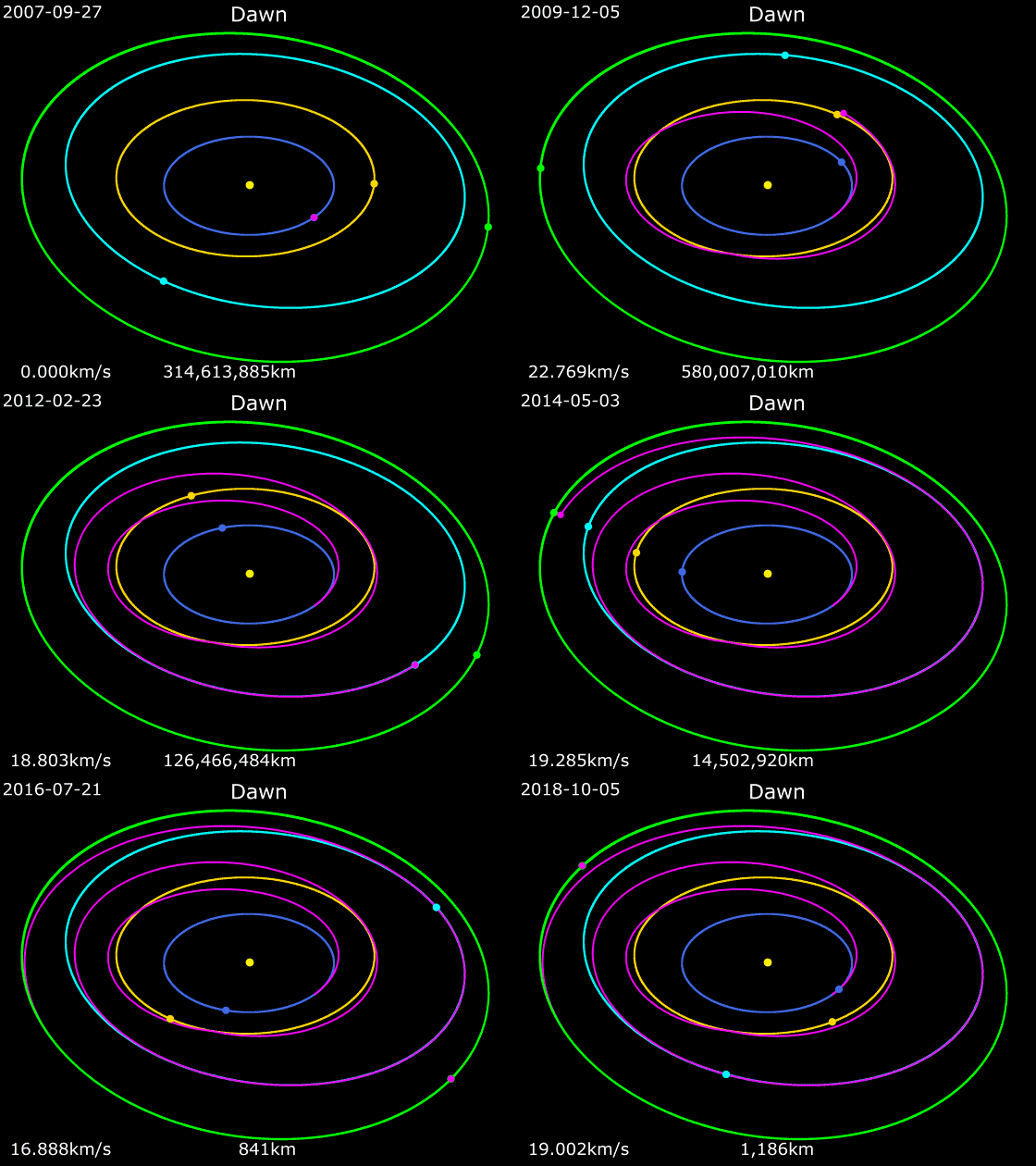
Dawn Spacecraft Earth Orbit Mars Orbit Vesta orbit Ceres Orbit

Key Facts

  • Dawn is the first spacecraft to orbit two destinations in space. 

  • The record powered flight: Ion propulsion was active for 5.9 years(54% of the time in space as of 7th Sept 2018).

  • Dawn was able to travel to 2 destinations for the price of one by using Ion-engine technology. 

  • Dawn's mission is the first to orbit a main-belt asteroid and the first to reach a dwarf planet.


Read More

December 31, 2020

Ingenuity: First Powered Flight on Mars

December 31, 2020 0

The first powered flight on another planet is scheduled for 2021. The small Mars helicopter is attached to the belly of the rover ‘Perseverance’. The mission will help us understand the future possibilities of utilizing aircraft on Mars.

Why Fly a Drone on another planet?

The Ingenuity’s primary objective is a ‘demonstration flight’ which is intended to understand the technologies needed for flying on the Red Planet. If the mission is successful, similar improved technologies such as advanced robotic flying vehicles can be utilized in the future exploration of Mars. Flying on Mars can offer a unique advantage especially to capture high definition images or reconnaissance for robots or even Humans and it can also enable access to difficult terrains for rovers.

Mars Helicopter Parts

  1. Solar Panel: The topmost part of the drone is where the solar panels are mounted which helps to charge the batteries autonomously. 

  2. Antennas: For communicating with Earth through the Mars 2020 rover and spacecraft in Mars’ orbit. 

  3. Rotor blades: Carbon fiber propeller blades to provide the necessary lift to the aircraft. 

  4. Batteries: 6 sony li-ion cells with 140 kilo-joules of battery energy capacity. 

  5. Fuselage: Holds the avionics system which consists of a number of electronic instruments used to perform the required flight controlled functions. 

  6. Sensors and camera: for surveillance and majorly for creating a feedback loop to help operate the aircraft autonomously. 

  7. Legs: Very lightweight legs made from carbon fiber tubes to land the aircraft after flights.


Height

0.49 meters

Rotor Span

1.2 meters

Weight

1.8 kg

Creating Mars conditions on Earth to Test Ingenuity

Two parameters needed to be altered to successfully create Mars conditions on our planet. 

  1. Gravity: The ‘Gravity Offload’ technique was used to fake the Martian gravity pulling down on this drone. This was achieved by using an appropriate fishing cord, a Brush DC motor, a Reaction torque sensor, and a pulley which was mounted on the ceiling of the space simulator and other end was attached to Ingenuity so that it weighed only 38% of its actual weight as if it was on Mars.

  2. Air Pressure: The ‘twenty-five-foot space simulator’ was used to generate Martian atmospheric pressures. To test the propeller blade’s ability to provide lift force in a thin atmosphere. 

Ingenuity Design Challenges 

Mars has a very thin atmosphere: In terms of density, about 1% of the atmosphere on Earth. And hence a lot of air has to be pushed downward to provide the necessary lift force. And to achieve this, The propeller blades onboard Ingenuity rotate at 2300 to 2900RPM.  Even at these RPMs, the blades are designed to reach a 0.7 Mach number in order to avoid the complex aerodynamic difficulties which arise in the case of supersonic flows at Mach 1 and beyond. 


The major challenge of designing Ingenuity was weight constraint. And hence every part is manufactured keeping in mind the total weight of aircraft. The propellers which are the largest parts on board weigh only 38 grams each. The insulation material for keeping the avionics compartment warm is carbon dioxide gas contained in a foil surrounding the compartment to save weight.

Key facts 

  • Flying Ingenuity on Mars is equivalent to Flying a similar helicopter on Earth at 100,000 feet. (Helicopters on earth have a record of flying at Max 40,000 ft.)

  • Mars Helicopter can fly up to 90 seconds and to distances of about 980 feet at a time while flying at 10 to 15 feet off the ground. 

  • Because of the time delay in Earth to Mars Transmission of signals, Ingenuity has to Take-off, Fly and Land on its own.


Read More

November 23, 2020

Voyager 1: The Farthest in Space

November 23, 2020 0

The first Human-made object to enter interstellar space. A probe launched by NASA to study the outer part of our solar system in the 1970s and is still up and working with some of its scientific instruments after leaving the solar system.  

The Spacecraft Construction

Three separate booms were attached to the central decahedral bus. A 3.66 m diameter(Parabolic) high-gain antenna was mounted on top of this Bus. 

  1. Science boom: Extending out 2.5 m from the bus, had Steerable scan platform with imaging and spectroscopic remote sensing instruments at the end. Plasma and charged particle detectors were placed at various distances along this boom. 

  2. Magnetometer boom: A separate 13 m. long boom opposite to Science boom had Magnetometers.

  3. Generator boom: A third boom extending down and away from the science boom holding the power source of the spacecraft(RTGs).

Two whip antennas (10 m each) also extended from the spacecraft for plasma wave and planetary radio astronomy investigations.


The Power source 

Three Radioisotope Thermoelectric Generators(RTGs) were used to provide power to Spacecraft systems. Each RTG contained Plutonium-238 in the form of plutonium oxide enclosed in a casing of beryllium (Length: 50.8 cm, Diameter: 40.6 cm, Weight: 39 kg.).


Plutonium oxide generated heat as it decayed and a bimetallic thermoelectric device was used to convert this heat into electric energy for spacecraft instruments. The initial output of the RTGs was 470 W of 30 V DC power at launch but it kept decreasing as more Radioactive material was expended.


Mission Timeline

Launch: Sept. 5 1997 from Cape Canaveral, Florida onboard Titan IIIE-Centaur launch system. With a primary mission of exploring Jupiter and Saturn. 


Exploration of Jovian system: The closest encounter(280,000 km) of Voyager 1 to planet Jupiter was on March 2, 1979, but the imaging of Jovian system had already started in April 1978. At the beginning of January 30, 1979, Voyager took pictures of Jupiter every 96 seconds for a total of 100 hours allowing us to generate colour timelapse of 10 rotations of Jupiter.


Voyager 1 also captured incredible images of several of Jupiter’s moons during the flyby: Amalthea (420,200-kilometer range), Io (21,000 kilometers), Europa (733,760 kilometers), Ganymede (114,710 kilometers), Callisto (126,400 kilometers) and also discovered two new moons: Thebe and Metis.


The spacecraft made two course corrections after encountering the Jovian system to move to the Saturn system one of which was on April 9, 1979. And the second on Oct 10, 1979, was specifically for avoiding its trajectory to hit the Titan.

Exploration of Saturn System: The closest approach to planet Saturn was on Nov. 12 1980 within a range of about 126,000 km. During this, Voyager 1 found 5 new moons around the planet and also thousands of bands in the rings of the planet with shepherd moons which keep the rings well-defined.


It also photographed moons of Saturn: Titan, Mimas, Enceladus, Tethys, Dione, and Rhea. with the close approach to Titan at around 4000 km on November 12, 1979. Which revealed incredible details about the moon with a thick atmosphere and a possibility of liquid existing on the surface.


Boundaries of Solar System: The planetary encounters were over after a visit to Saturn’s system, and Voyager 1 was set on a trajectory to leave our solar system with a speed of about 523 million km per year(59,703 km/hr). On December 16, 2004, spacecraft showed an indication of crossing the termination shock and entering into the Heliosheath. And it finally exited the solar system on August 25, 2012, and set the record for human-made spacecraft to ever leave the Solar system. 


Before this record, on February 14, 1990, Voyager 1’s cameras were pointed Backwards to take the first ‘Selfie’ of our Solar System from a distance of 6 billion km(40 Astronomical Unit) from the Sun. The image was later known as ‘Solar System Family Portrait’ with no Mercury as it was too close to Saturn and only the dark side of Mars was visible.


Key Facts

  • On February 17, 1998, Voyager 1 overtook Pioneer 10 at a distance of 69.4 AU from the Sun to become the most distant object sent into space by humans. 

  • Voyager 1 was launched 16 days after the launch of Voyager 2 but it was on a faster route and overtook Voyager 2 on December 15, 1977.


Key Resources:


Read More

July 27, 2020

Chandra X-Ray Observatory

July 27, 2020 0

Launched aboard space shuttle columbia from Kennedy Space Center on 23rd July 1999, The Observatory is named after a Nobel Prize winner, Indian-American astrophysicist Subrahmanyan Chandrasekhar. The telescope is specifically designed to observe the X-Ray sources in the universes such as Galaxy clusters, exploded Stars, and matter around Black Hole. 


Chandra Specifications


Overall Size

13.8m x 19.5m (45.3ft x 64 ft)

Overall Weight 

4800 kg (10582 lbs)

Telescope Weight

956.4 kg (2108 lbs)

Focal Length

10m

Telescope outer Diameter 

1.2 meters (3.9 ft)

Field of view 

1 degree diameter

Angular resolution

0.5 arcsec

Transmitter Frequency

2250 MHz

Receiver Frequency 

2071.8 MHz

Pointing Accuracy 

30 arcsec

Power 

Two 3 panel solar arrays (2350 W) three 40 amp-hour nickel hydrogen batteries 


How Does it Observe?

Earth’s atmosphere absorbs most of the X-rays, Being Above this obstacle allows Chandra to analyze spectra of cosmic sources. Four sensitive mirrors which are nested inside each other, focus the energetic X-rays onto a tiny spot (about half as wide as a human hair!) at the end of the optical bench at about 9.2 meters on the focal plane. Here, Electronic detectors generate sharp images that provide information about the X-rays such as Position, number, Energy, and time of arrival.


Chandra's Hardware Components

This Observatory can be divided into its three major parts:

  1. Telescope system: This includes a support structure and four nested mirrors (which look like barrels) kept almost parallel to each other and parallel to incoming X-rays for deflecting them into the electronic detectors.  

  2. Science instrument: Consists of ACIS(Advanced CCD Imaging Spectrometer), HRC (High Resolution Camera), High Energy Transmission Grating (HETG) Spectrometer, Low Energy Transmission Grating (LETG) Spectrometer. 

  3. Spacecraft: This includes 2 different sets of thrusters(One for Propulsion and other for Applying torque), Chandra’s Thermal Control system (Insulators, Heaters, Cooling radiator, Thermostats) and its two solar arrays.


Science Instruments

  1. HRC (High-Resolution Camera): HRC is one of the scientific instruments used at focal plane where X-Rays are detected. There are two MCP (Micro Channel Plates) consisting of a cluster of millions of tiny lead-oxide glass tubes (each about 1/8th of a thickness of human hair and 1.2 meters in length). Special coating on the tubes makes it release electrons when X-Rays are struck and these electrons are accelerated down the tube by high voltage releasing even more electrons. The cross grid wires detect this electronic signal and allow astronauts to construct a detailed map of the X-Ray source. 
  2. ACIS (Advanced CCD Imaging Spectrometer): It is another focal plane science instrument of Chandra, consisting an array of Charged Coupled Devices (CCD) which is basically a light-sensitive integrated circuit but highly sophisticated version. It can measure the energy of incoming X-Rays and produce images and thus, allowing us to examine the temperature variations across different X-Ray sources such as hot clouds of gas and remnants of supernova explosions.
  3. High Resolution Spectrometers (HETG and LETG): This is an assembly of hundreds of gold transmission gratings placed behind the mirrors. These grating diffract the incoming X-Rays where, the change in the direction is proportional to the energy contained within X-Ray. These distinguished X-Ray lines enable analysis of temperature, ionisation and chemical composition of the source.

Fun Facts

  • During maneuvers from one target to another, Chandra turns slower than the minute hand on a clock. 

  • The mirrors onboard Chandra are so smooth that if they were earth sized, the highest mountains would be 2 meters tall! 

  • The electrical power requirement of Chandra is about the same as a hair dryer. 

  • Some of the Light Observed by Chandra will have been travelling through space for ten billion years. 

  • Chandra is powerful enough to read a stop sign at a distance of twelve miles.


Read More

July 18, 2020

Spitzer Space Telescope

July 18, 2020 0

The Telescope was named after an American theoretical physicist and Astronomer Lyman Spitzer. It was launched aboard Delta II rocket in August 2003, with a mission period of 30 months. After completely exhausting the cooling system required for full operational capability in May 2005, most of the equipment was declared unusable and shut down. But some of the scientific equipment continued working until January 2020. 


Spitzer Specifications

Total Weight (At launch)

950 kg (2094 lbs)

Helium mass 

50.4 kg (111 lbs)

Nitrogen Propellant 

15.6 kg (34.4 lbs)

Diameter

85 cm (2.79 feet)

Imaging Photometry 

3-180 Microns 

Spectroscopy 

5-40 Microns

Spectrophotometry

50-100 Microns

Planetary Tracking 

1 arcsec/sec

Liquid Helium volume 

360 liters (95 Gallons)

Diffraction limit 

1.5 arcsec at 6.5 Microns 

Orbit 

Heliocentric


What does it sense?

Any object in space having a temperature above 0 Kelvin (-273.15 degrees Celcius) emits infrared radiation. Human eyes are not able to see these radiations, but we can feel it as heat. The Spitzer was specifically designed to observe the infrared light emitted by Galaxies, Exoplanets, and Stars deep into space. To avoid interference between its own body temperature and its observations, the telescope, and its detectors were cooled down to a temperature of 5 kelvin (-268 degrees Celsius).


Spitzer's Structure


As contradictory as it may sound, The Spitzer needed to be at room temperature as well as at -268 degrees Celsius simultaneously for the reason mention above. And hence the Spitzer’s structure was separated into 2 different components. 

  1. Cryogenic Telescope Assembly(CTA)

  2. The Spacecraft

The CTA was attached to spacecraft using special insulating struts and a number of thermal radiation shields to prevent heat from spacecraft to reach to the Telescope. 


Cryogenic Telescope Assembly consisted of the Telescope, Cryostat, Outer Shell Group, and Multiple Instrument Chamber which included Infrared array camera, Infrared Spectrograph, and Multiband imaging photometer. Liquid Helium in the Cryostat tank acted as a coolant that produced freezing vapor to cool the CTA down to -268 degrees Celsius. The outer shell was made from aluminum. It was shiny to the side facing the Sun and was painted black on the side facing away from the Sun in order to reflect the Sunlight and radiate heat as much as possible. 


The Spacecraft consisted of 2 parts, Solar Panels, and Spacecraft Bus. Solar Panels were used to generate electrical power for the instruments on the spacecraft and also to shield the telescope for the Sun. Spacecraft Bus was an octagonal structure consisting of data handling units, reaction control subsystem, telecommunication subsystem, power generation, and distribution subsystem, flight software. These instruments performed engineering functions such as Communication with ground control here on Earth, Telescope Stabilization, and Orientation in the desired direction, providing electrical power to science instruments.


Science Instruments

Infrared Spectrograph: Each element in the Universe has its own unique light signature. IRS breaks the incoming Infrared light into different spectrum and allows astronomers to detect what the object is made up of. IRS has 4 modules with a separate entry slit on each to allow infrared light to enter into spetrograph.
  1. Low-resolution, Short-wavelength module with Detecting Range 5.3 - 14 microns
  2. Low-resolution, Long-wavelength module with Detecting Range 14 - 40 microns
  3. High-resolution, Short-wavelength module with Detecting Range 10 - 19.5 microns (High Details)
  4. High-resolution, Long wavelength module with Detecting Range 19 - 37 microns (High Details)
Infrared Array Camera: Imaging camera customized specifically for wavelengths from 3.6 to 8.0 microns. It has 4 different detectors which simultaneously takes image of 3.6, 4.5, 5.8, 8.0 microns of wavelength. Camera shutter is the only moving part on the entire IARC instrument. 3.6, 4.5 micron detectors are made from indium and antimony while 5.8, 8.0 micron wavelength detectors are treated with arsenic. 
Multiband Imaging Photometer: Imaging camera customized for far Infra-red wavelengths: 24, 70 and 126 microns. 24 micron detector is made up of silicon and specifically treated with arsenic. 70 and 160 micron arrays are made of germanium treated with gallium. Scan mirror is the only moving part of the MIPS which is used for mapping large areas of the skies. 
Read More

Post Top Ad

Your Ad Spot